HOW I FIXED MY HUMANOID ROBOT
one leg on my Unitree G1 kept dropping off the motor bus. the app reported PC to Motor Timeout on five actuators. the likely fault was a single kinked comm cable at the hip harness entry. full diagnosis, photos, and a triage procedure for other G1 owners.
One leg on my Unitree G1 had an intermittent fault, and the pattern was specific: it only ever failed at power-on. Some boots the leg came up dead and the app filled with motor alarms. Other boots it came up fine, and once it was up it never dropped mid-session, not even walking. The other leg, both arms, and the waist were unaffected. This weekend a hardware engineer friend and I put it on his bench and traced it. This post is the diagnosis, the teardown, the relevant Unitree documentation with direct links, and the caveats. Target reader: someone who owns or maintains one of these.
Symptoms as reported by the robot
The Unitree app's Alarm Information panel logged six entries with the same timestamp: Motor 1 through Motor 5, each with "PC to Motor Timeout", plus "Communication firmware error: Motor Data Timeout". Identical timestamps across five actuators is the first tell. Independent motor failures don't synchronize.
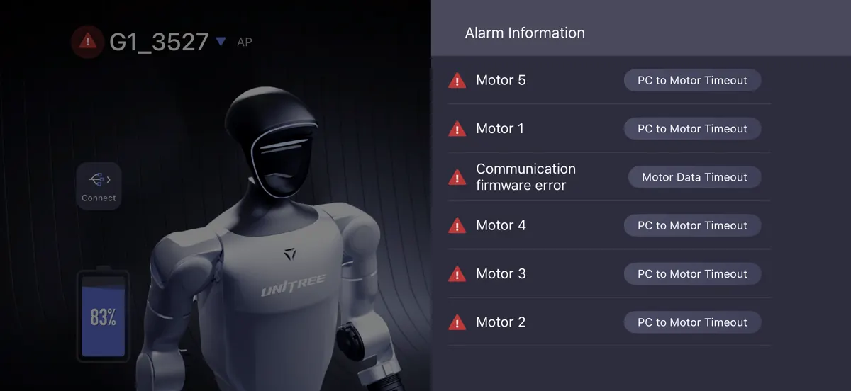
PC to Motor Timeout means the main compute board sent a command frame to that actuator's driver and never received the status frame back within the deadline. The actuator driver itself may be alive. What's proven dead is the round trip.
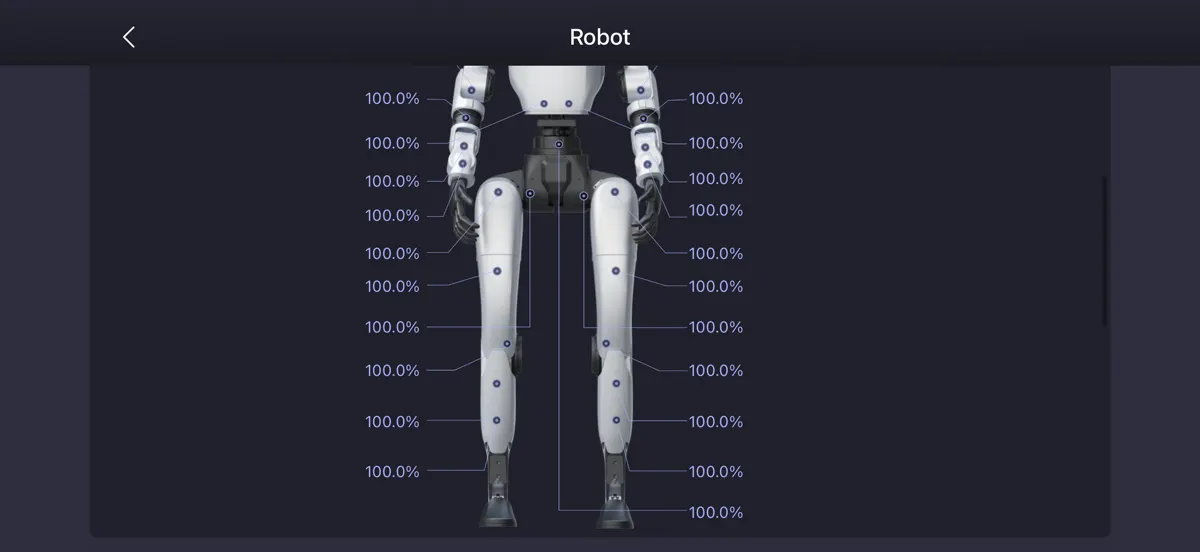
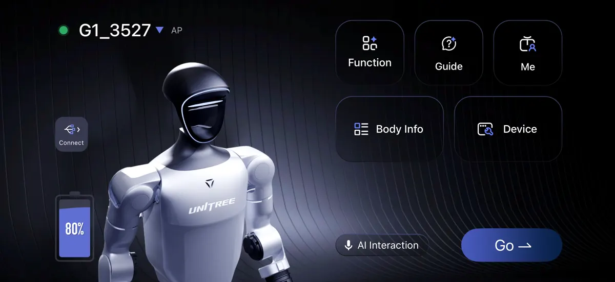
Body Info, Motor Information, Communication Quality shows per-joint link quality. Five of the six actuators on one leg read 0.0%, starting at the hip, with one mid-leg joint oddly still at 100%. The other leg and both arms read 100% everywhere. So the loss starts at the hip and takes nearly everything distal to it.
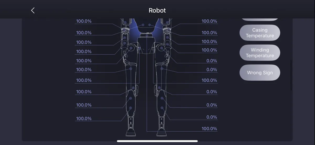
Note on the diagram: the model faces you, so the screen-right column is the robot's left side. Map it to motor indices from the SDK low-state topic before you trust which leg is which. I didn't log the indices during the session, which I regret.
Also: the robot's face LED ring flashes red fast in this state. That's a system-level fault indicator. It tells you a motor fault exists; it tells you nothing about which limb.
Fault tree
Five simultaneous timeouts on one limb, starting at the hip, leaves three candidates: a dead actuator driver acting as a broken link in the chain, a power drop to that leg, or a fault in the comm path where the leg's harness enters the pelvis.
Power was easy to narrow down. With the robot on, the actuators on the dead leg still had their board LEDs lit and ran their startup blink, so board power was present. That's not a voltage measurement and it doesn't exclude a brief dip during boot, but it moves the weight toward the comm path. A fault that comes and goes made a mechanical connection fault more likely than a dead driver, without excluding one. The power-on-only pattern is the part that doesn't fit neatly: a conductor that opens under flex should also drop out while walking, and mine never did. That keeps a boot-time cause, like a marginal contact that only matters during bus enumeration or a brief supply dip, on the table.
Prior art: the Munro Live teardown
Two days before we opened the robot, Munro Live published a 26-minute teardown of the G1's actuators with Paul and Armin from Munro & Associates: https://youtu.be/CSJydnLzBAo. It's the most detailed public look inside these actuators I've found. We used it to learn the internal layout before opening anything: what the stator, rotor, two-stage planetary gearset, and control board look like, where the driver board sits relative to the output, and how the wiring flows through the actuator. The fabric tape and what was under it we found ourselves on the bench; the video doesn't cover that.
The part that matters for this fault starts at 20:09, "How do you get electricity to a thing that is rotating?" Paraphrasing Paul: running a separate wire from the battery to each of 24 actuators would cost as much as the rest of the robot, so Unitree runs power and signal down the center of each actuator through one bundle, and the motors are daisy-chained: the power of one exits and goes to the next. The trouble is that the harness has to twist. Hard stops keep it under 360°, but it goes about 350° one way then the other, and over many cycles that fatigues the copper and eventually causes wires to break. They use very small stranded wires in individually insulated bundles to survive it, and he puts the design at roughly a couple hundred thousand cycles. For millions of cycles you'd need something like an automotive clock spring.
So the harness fatigue failure mode isn't my theory. It's the one the teardown engineers name as the known limit of this design. Also useful: at 15:48 he shows the control board and the small wires that carry the torque command in, which is the comm side of the bundle we were chasing.
Differential: healthy hip vs dead hip
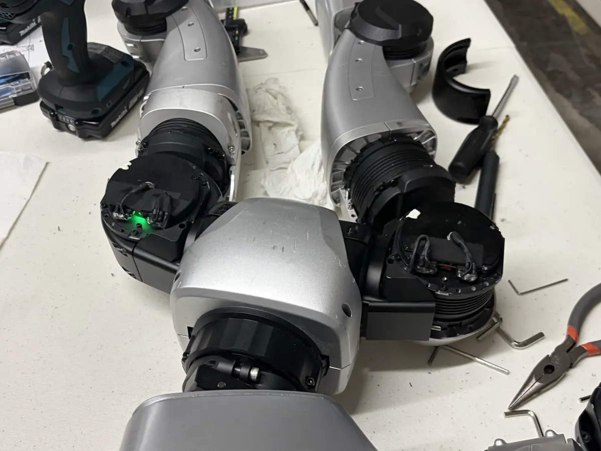
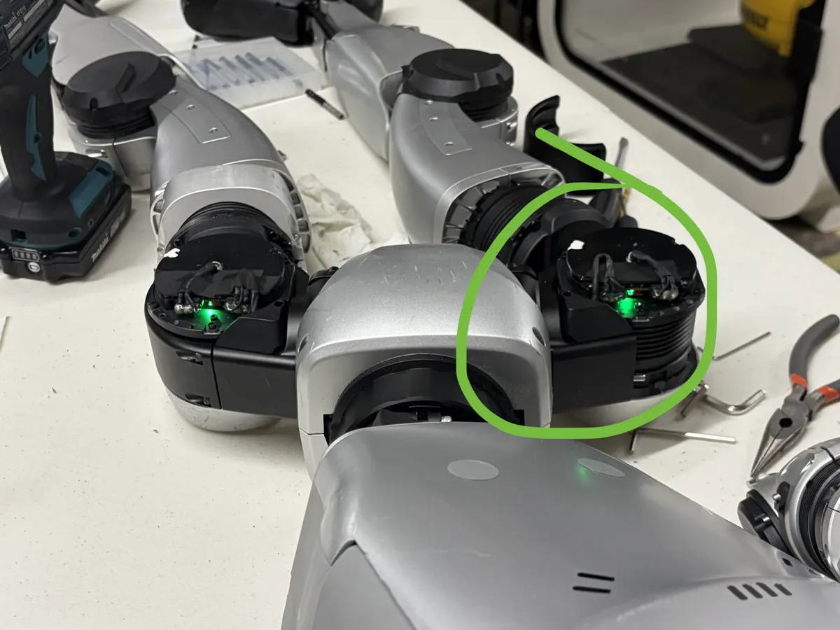
We opened both hip actuators so we had a known-good reference next to the suspect. The driver board on each actuator has a status LED. On the healthy side it gave a brief, slow blink. On the dead side it blinked rapidly. Unitree publishes no LED table for the G1 motor boards, so I can't tell you what the rapid blink encodes (waiting for the bus, repeated reset, or something else). The difference was the useful part: same part number, same harness, two different states.
Under the tape
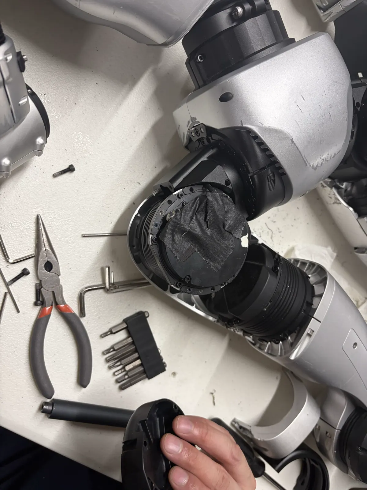
The actuator face is wrapped in black fabric tape. Underneath are the two harness terminations onto the driver board: power and comm. Both are secured at the board with what looks like hot glue and heat-shrunk up the lead.
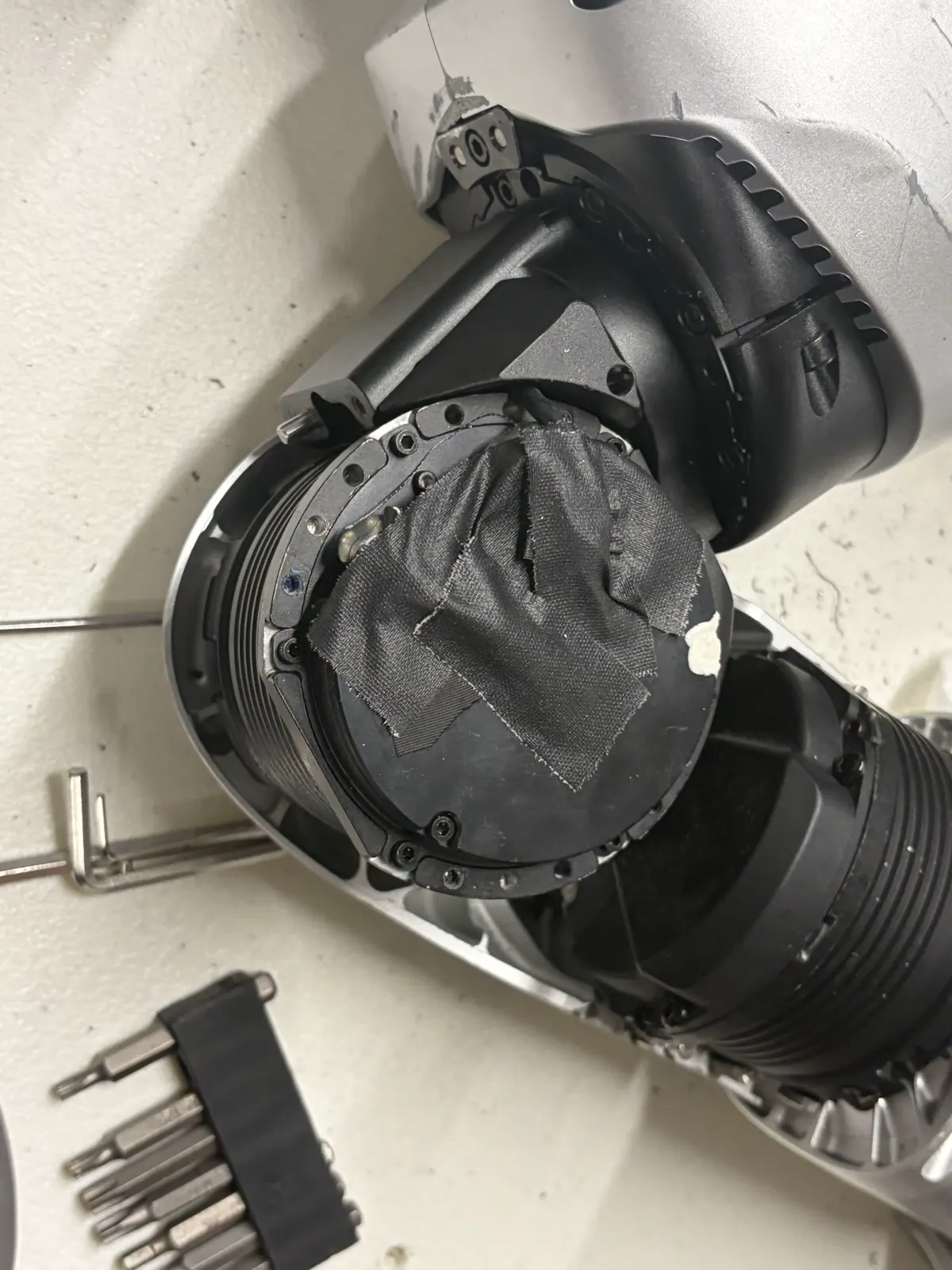

Visual inspection on both sides came back clean, which is the expected result for a conductor fractured inside intact insulation. A flex-fatigue break is invisible from outside. Under one bend radius the strands touch and the link is up; under another they separate and the link drops. That's exactly the intermittent behavior we had.
The harness entry
A small triangular cover sits where the harness passes from the hip actuator into the pelvis. We removed it. Behind it, the comm lead makes a tight bend up and over the actuator's mounting plate, directly against an unrelieved edge of the housing, and the lead is free to rub on the inside of the hip shell through the joint's range of motion. Three failure mechanisms in one spot: tight bend radius, edge contact, and cyclic abrasion. Past this point the harness runs into the pelvis, so we stopped there.
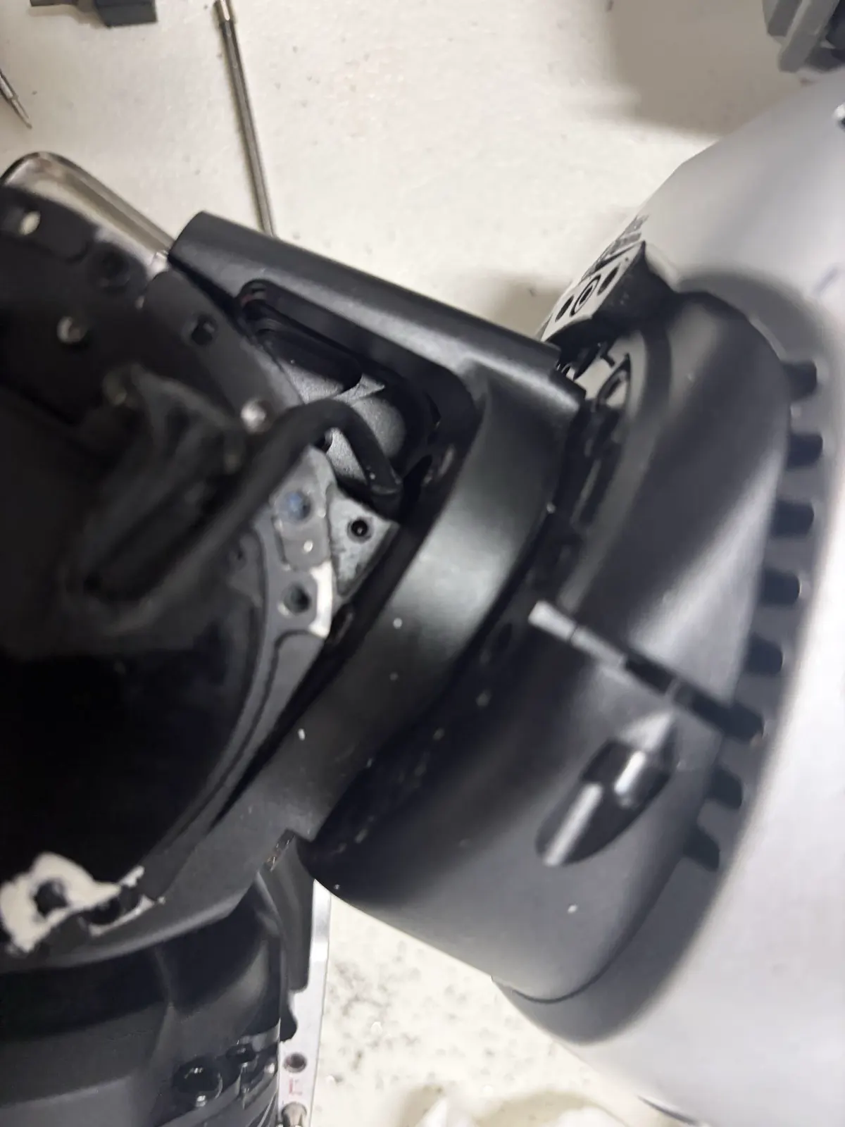
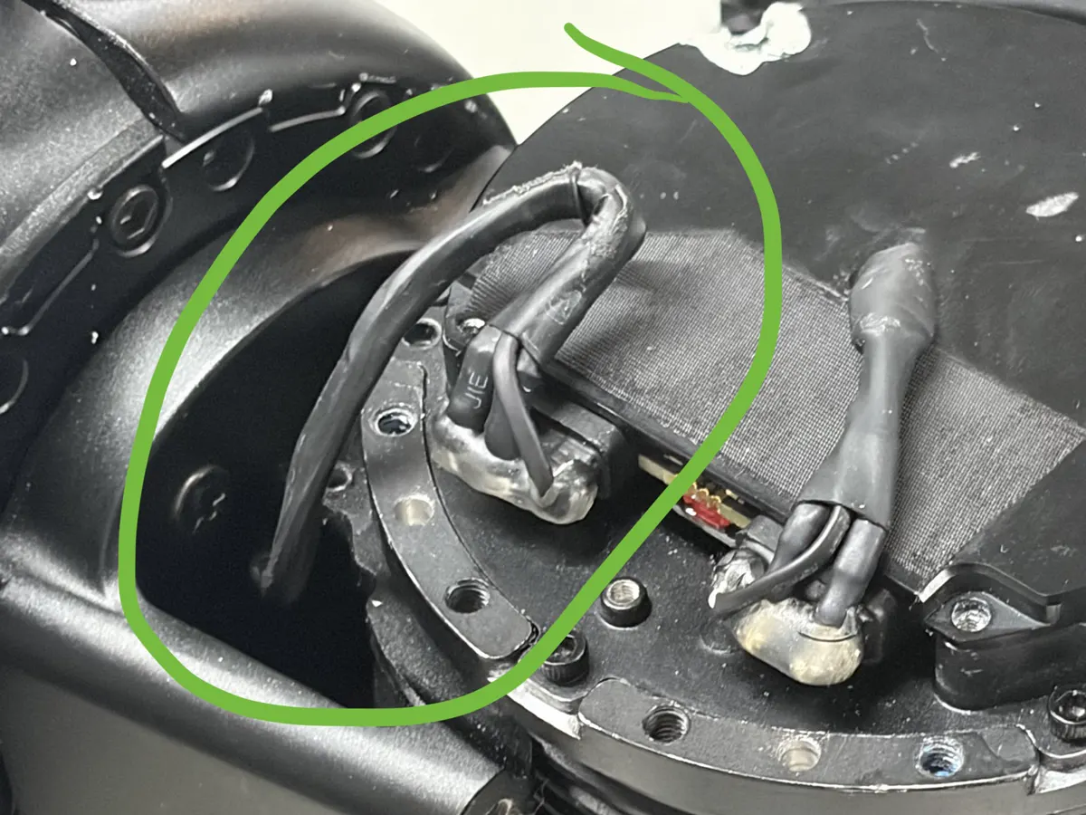
Removing this and tinkering with this fixed the entire problem. Most likely the damage is these weird little bends right here.
We disconnected the comm connector at the hip, reseated it, and powered on. Every joint reported 100% link quality. No alarms. The robot was fully up.
What this does and doesn't prove
Reseating fixed the symptom. It doesn't isolate the cause between a fractured conductor at the kink and a marginal contact at the connector itself. Both are consistent with the evidence, and the power-on-only history actually leans toward the connector: a contact that's marginal at rest but good enough once the bus is up would fail exactly this way, while a flexing conductor should have dropped mid-walk at least once. What's not consistent is a dead driver: the same board came up green with nothing changed but the connection. I'll only call it confirmed after the cable and connector are replaced and the fault stays gone across many power cycles.
On the bus topology inside the leg: Unitree's doc (below) says the motors are wired in a chain on the RS485 bus, and the Munro teardown confirms the physical side, power and signal exit one actuator and enter the next. What neither says is whether each driver board electrically forwards the RS485 pair or all boards hang off one shared pair that just passes through. Either way, an interruption at the hip takes out everything past it. If you've mapped the actual pinout, I want to hear from you.
What Unitree's own documentation says
The primary source is Unitree's own help-center article "G1 APP常见报错" (G1 app common errors), last updated 2026-04-20: https://serviceconsole.unitree.com/#/help/011325 (Chinese; the help center is a slow single-page app, give it a few seconds). Under the heading "PC连接电机超时", which is what the English app renders as "PC to Motor Timeout", it distinguishes two cases. My translation:
- Case 1, a single motor reports PC connection timeout: the driver of that motor may be abnormal. Try calibrating that limb, return it to the normal position, restart, and see if the error clears. If it doesn't, the motor is faulty; contact after-sales to return it for repair.
- Case 2, every motor on one arm or one leg loses connection: because the robot's motors are connected in series (串联), a whole limb dropping out may be the motors' RS485 communication line disconnected at some segment. Check the G1's surface wiring for damage or looseness and try reconnecting the cable. But the G1 routes wiring through hollow internal structure, so if inspection finds nothing, contact after-sales to return it for repair.
RS485 is a differential serial bus: the receiver reads the voltage difference between two conductors, and many devices share the same pair. Power and data are separate requirements, which is exactly why a motor board can light its LED and still be unreachable. One broken conductor or one bad contact on the pair isolates every device past it.
3Logic Group's G1 knowledge base (a Russian Unitree distributor) has a matching entry under "Основные проблемы и ошибки": https://robodocs.3logic.ru/docs/Unitree%20Robotics/G1/g1_quick.html. My translation: "The robot's LED is solid red, and in the app an entire limb is missing from Communication status. Problem with one of the motors in the limb's chain. In the case of a leg: damage to the waist communication cable during installation or removal of the waist brace. Contact after-sales support." 3Logic doesn't say which LED it means; don't map that to the actuator boards or the face ring from this quote alone. The useful part is the second inspection zone: the waist-to-pelvis run, on top of the hip entry.
Unitree's G1 error-code table ("常见错误及释义", 2024-10-25) defines the flags behind the app text: https://support.unitree.com/home/zh/G1_developer/common_istakes_and_definitions. Two tables: device-status and motor-status. In the device-status table, 0x8 is "电机反馈数据超时" (motor feedback data timeout), which is the "Motor Data Timeout" line under "Communication firmware error" in the app. The motor-status flags worth pulling from the SDK low-state topic during a failure:
- 0x8: 瞬态欠压, transient undervoltage on the motor.
- 0x4000: abnormal reset of the motor controller.
- 0x40000: communication checksum error (corrupted frames detected).
- 0x40000000: motor detects PC connection timeout (motor reports the computer went silent).
- 0x80000000: PC detects motor disconnection timeout (the computer reports the motor went silent). This is the flag behind the app's "PC to Motor Timeout".
Caveat on those flags: a motor that can't reach the bus also can't report its own undervoltage or reset bit, so a missing flag doesn't clear that fault. Also note the overall device-status field reuses some of these numbers with different meanings.
How these were found: I fed the app screenshots, the teardown video, and my observations to ChatGPT and asked it for GitHub issues, forums, and official docs. It surfaced the Chinese article and the RS485 chain detail. Every source above is linked directly, and the quotes are translated from those pages, not from the chat. The chat is public if you want the trail: https://chatgpt.com/share/6aa7acd1-f974-83e8-b1ac-c406ae8023e4
Triage procedure if your G1 does this
- Pull the alarm log. Note which motor indices report PC to Motor Timeout and whether the timestamps match. Synchronized timeouts on one limb point at the link, not the actuators.
- Open Body Info, then Communication Quality. Find the most proximal joint reading 0%. The fault sits between it and the last healthy joint.
- Confirm board power at the dead joints: their driver LEDs should light. Dark LEDs mean a power problem, and this post won't help you. Lit LEDs don't prove clean voltage, only that some supply is present.
- Watch the Munro Live teardown, especially 20:09 onward, so you know the internal layout and how the harness flows through each actuator before you open anything.
- Open the suspect hip and the healthy hip. Compare driver board LED behavior side by side. On mine: brief slow blink on the healthy board, rapid blink on the dead one. Also pull motor-status flags from the SDK during a failed boot and check Motor 0, which Unitree's guidance uses to decide whether the break is at the hip or upstream.
- Peel the fabric tape and inspect both terminations. Expect them to look fine. A flex break hides inside the insulation.
- Remove the triangular cover at the pelvis entry. Inspect the bend radius, edge contact, and any abrasion on the comm lead. Do not go into the pelvis.
- Reseat the comm connector. Power on. Recheck Communication Quality. If it comes back, you've localized the fault, not repaired it.
- Re-tape, reassemble, and schedule a real repair: replace or re-route the lead and add strain relief at the entry.
Open items
The lead is still kinked. Reseating bought time, not a fix. The permanent repair is a replacement harness section with a proper bend radius at the pelvis entry and a grommet or sleeve where it crosses the housing edge.
Blocking that: several of the M3 socket-head screws on the hip housing are stripped. Plan is to cut a slot into each head with a rotary cutoff wheel and back them out with a hand flathead, then replace with new hardware. I'll document that pass separately, including the part number for the harness if Unitree will give it to me.
If you own a G1 and hit this, reply to the newsletter or find me on X. I'd love to compare notes. There aren't many of us opening these things up yet!